[This article was originally published in the Fox Cities Amateur Radio Club’s QSOer newsletter.]
Don’t tell the other mechanical engineers, but Chris, N9CVR, has an electronics addicti—er, hobby. His dad introduced him to it at a very young age; at age 5, he was taking apart garage sale VCRs for fun. But he never really progressed past plugging wires into a breadboard and hoping it works, until he was given a small, empty, circuit board by club VP Andy, AJ9L. He eventually specified the parts for it, and built a cascade effect pulse generator. And thus, the demon was unleashed.
Being an engineer, Chris wanted to standardize his radio shack, so when he learned how heavily Anderson Powerpoles are used in the ARES/RACES community, he started work on switching his radios over. But he struggled to find a good, portable solution for fuses. It seems everyone else either chopped up the cable that came with their radio, or bought large, heavy distribution blocks. This sounded like an easy DIY project!
And it was…sort of. His first challenge was designing a printed circuit board (PCB). During the pulse generator project, Chris had learned of the existence of PCB printing houses (Oshpark and PCBWay are two examples). The boards are printed from Gerber (.grb file extension) files, which can be created using special electrical CAD software. There are many options for PCB design software, but one stood out to Chris – KiCad. KiCad is a free, open-source, full featured PCB design suite which runs on Windows, Mac and Linux. On top of that, DigiKey and Shawn Hymel, formerly of SparkFun Electronics, have put together a playlist of 10 easy-to-follow YouTube tutorial videos (just search ‘kicad tutorial’ and it’ll be the first link) which take you through the entire design process.
But, Chris was getting ahead of himself. In order to design a PCB layout, you need to know not only what components you’ll be using (e.g., a Powerpole connector), but also its shape, lead spacing, etc. This meant specifying the parts for the fuse block. This meant combing through various electronics supply web catalogs for parts that would work, then comparing them across suppliers to ensure lowest cost. Then it was back to KiCad to make the final layout. This layout got exported into Gerber files, zipped up, and sent to the PCB manufacturer.
About a week and a half later, Chris had all of the components to build his first prototype. He put them together and…they didn’t work as he had expected. Chris went back to the parts catalogs, combed through datasheets and found parts that would work better. He then made the appropriate modifications in KiCad. Round 2 of boards was sent out for manufacture, Round 2 of parts came in, and were delivered another couple weeks later (shipping from China can take a while!). This time, the design worked!
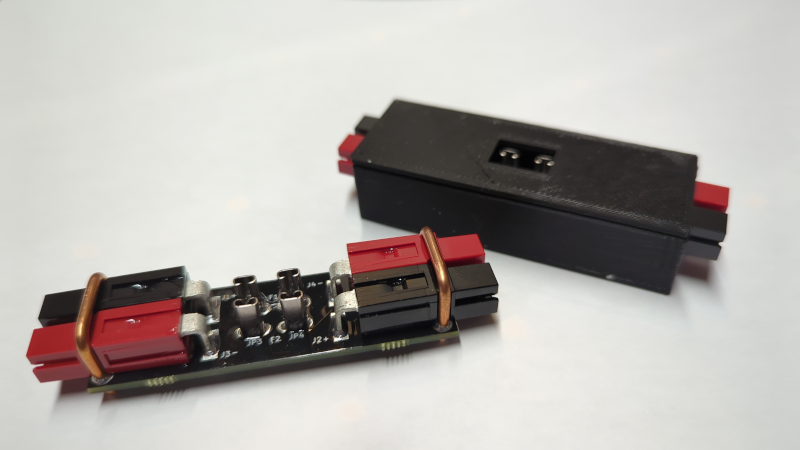
However, Chris was far from done. Components on a bare PCB are very lightweight, which is great for QRPers, but most hams, Chris included, would rather a nice enclosure, to protect the board in case of a surprise downpour. Chris has spent many years using Solidworks 3D CAD software, so this wouldn’t be a challenge. Wrong again! Solidworks is VERY expensive, and has very strict licensing terms regarding commercial use. As it turned out, though, free, open-source 3D CAD software also exists in the form of FreeCAD. Using FreeCAD, Chris designed an enclosure.
Getting started injection molding plastics is prohibitively expensive – designing and machining a molding die can cost tens of thousands of dollars. In the past few years, however, 3D printers have become accessible to hobbyists, so Chris settled on printing his enclosure. This was (and continues to be) probably the most complicated part of the entire fuse block project. While a 3D printer can be bought for less than $200, Chris has struggled to keep his printing reliably for a variety of reasons, which could fill an entire article on their own.
However, after all that, the result is a roughly 3.5in by 1in by 1in inline Powerpole fuse block that Chris has un-creatively named the [Fuse Block]. It weighs less than one ounce with fuses installed. It was a great learning experience – he learned several pieces of software, got a great insight into the electronics design process and learned a LOT about 3D printing (often the hard way). Chris has made the FB001 in various styles – a finished fuse block, a kit with a link to print your own enclosure and a kit with a pre-printed enclosure, for those who don’t have a 3D printer.

